CONTENT
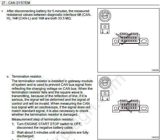
CAN SYSTEM
GENERAL INFORMATION
– System Description
– Operation
– Composition
– Tools
DIAGNOSIS & TEST
– Problem Symptoms Table
– Diagnosis Procedure
– DTC Confirmation Procedure
– Intermittent DTC Troubleshooting
– Ground Inspection
– Failure Analysis Method
– Common Troubleshooting
– Matching Learning
– Write Software Configuration Information
ON-VEHICLE SERVICE
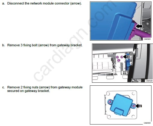
– Gateway Module (CGW)
– Removal
– Installation
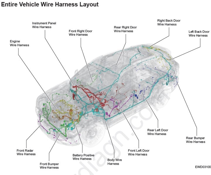
ELECTRICAL WIRING ROUTING
GENERAL INFORMATION
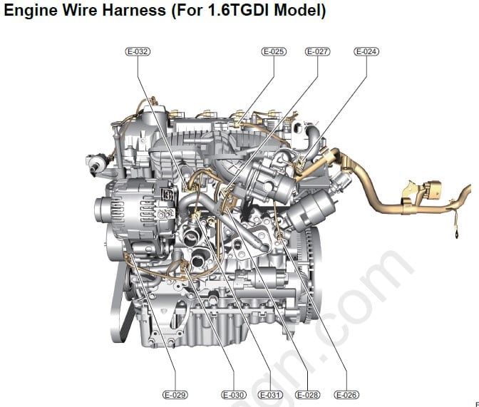
– Engine Wire Harness (For 1.6TGDI Model)
– Battery/Ground Wire Harness
– Front Bumper Wire Harness
– Front Radar Wire Harness
– Instrument Panel Wire Harness
– Body Wire Harness
– Front Left Door Wire Harness
– Front Right Door Wire Harness
– Rear Left Door Wire Harness
– Rear Right Door Wire Harness
– Back Door Wire Harness
– Rear Bumper Wire Harness
– Auto A/C System Wire Harness
– DCT Gearbox Wiring Harness
ENGINE MANAGEMENT SYSTEM (SQRF4J16)
GENERAL INFORMATION
– System Basic Principle
– Precautions for Engine Management System
– Basic Management Function of Engine
– Basic management function of engine
– Additional function
– Diagnosis on-line OBD
– Torque Structure: System based on torque control
– Control Signal: Input/Output Signal of Engine Management System
– Main sensor input signals of ECM in engine management system consists the followings
– Required actuator control signals which are generated via ECM from sensor input signals in engine management system includes the followings
– System Function
– Start control
– Intelligent start and stop control
– Heating control of engine warm-up and threeway catalyst
– Acceleration/deceleration and motored fuel cut-off control
– Idle control
– λ closed-loop control
– Evaporative emission control
– Knock control
– High pressure fuel pump control
– System Malfunction Diagnosis Function Introduction
– Malfunction information record
– Malfunction light description and its control strategy
– Diagnostic tester display
– System features
– Control Strategy
– A/C control strategy
– GPF malfunction light illumination strategy
– Fan control strategy
– Three-way catalytic converter protection control strategy
– Canister solenoid valve control strategy
– Oxygen sensor heating logic
– Knock control strategy
– Ignition control strategy
– Fuel pump control strategy
– Cooling water pump control strategy
– Electronic thermostat control strategy
– Variable displacement oil pump control strategy
– Turbocharger control strategy
– Relief valve control strategy
– VVT solenoid valve control strategy
– Starter protection function
DIAGNOSIS & TEST
– Diagnostic Trouble Code (DTC) Chart
– DTC Diagnosis Procedure
ON-VEHICLE SERVICE
– Electronic Throttle Body
– Description
– Operation
– Throttle Self-learning
– Common Problem Symptoms and Judgment Methods
– Removal
– Installation
– Vacuum Sensor
– Description
– Installation Position
– Operation
– Common Problem Symptoms and Judgment Methods
– VVT Control Valve
– Operation
– Removal
– Inspection
– Installation
– Coolant Temperature Sensor
– Description
– Installation Position
– Operation
– Installation Precautions
– Removal
– Common Problem Symptoms and Judgment Methods
– Installation
– Knock sensor
– Description
– Operation
– Installation Precautions
– Removal
– Common Problem Symptoms and Judgment Methods
– Installation
– Oxygen Sensor
– Description
– Operation
– Installation Position
– Installation Precautions
– LSF Technical Parameters
– LSU Technical Parameters
– Common Problem Symptoms and Judgment Methods
– Removal
– Installation
– Camshaft Position Sensor
– Description
– Operation
– Installation Precautions
– Common Problem Symptom
– Removal
– Installation
Engine Speed Sensor
– Description
– Operation
– Installation Precautions
– Common Problem Symptoms and Judgment Methods
– Removal
– Installation
– Fuel Rail Injector Assembly
– Operation
– Precautions
– Common Problem Symptoms and Judgment Methods
– Removal & Installation
– Intake Pressure Sensor
– Description
– Operation
– Installation Precautions
– Common Problem Symptoms and Judgment Methods
– Removal
– Installation
– Desorption Pressure Sensor
– Description
– Installation Position
– Removal & Installation
– Ignition Coil
– Description
– Operation
– Technical Characteristic Parameters
– Problem Symptoms and Judgment Methods
– Removal
– Installation
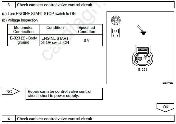
– Canister Solenoid Valve
– Description
– Operation
– Installation Precautions
– Problem Symptoms and Judgment Methods
– Removal & Installation
– Engine Control Module (ECM)
– Operation
– Installation Precautions
– Common Problem Symptoms and Judgment Methods
– Removal
– Installation
– Matching Learning
ENGINE MANAGEMENT SYSTEM (SQRF4J16.)
SYSTEM OVERVIEW
– Description
– SQRF4J16 engine has the following features
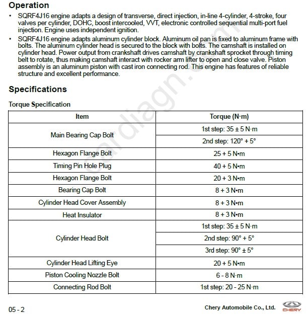
– Operation
– Specifications
– Lubrication Areas on Engine
– Seal Gum Application Areas on Engine
– Non-reusable Part
– Tools
DIAGNOSIS & TESTING
– Problem Symptoms Table
ON-VEHICLE SERVICE
– Accessory Pulley
– Removal of Accessory Drive Belt
– Inspection
– Installation
– Idler Pulley Assembly
– Removal
– Inspection
– Installation
– Tensioner Assembly
– Removal
– Inspection
– Installation
– Cylinder Head Cover
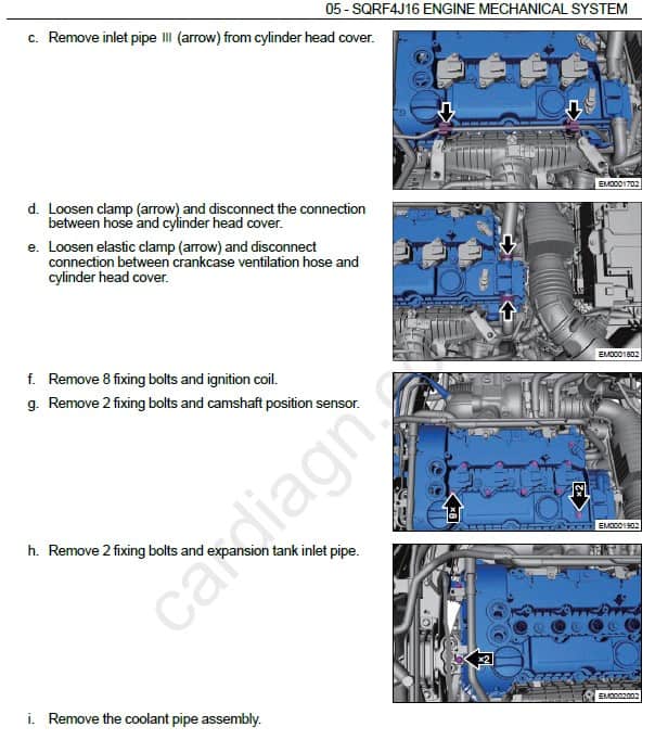
– Removal
– Installation
– Crankshaft Front Oil Seal
– Removal
– Installation
– Crankshaft Rear Oil Seal
– Removal
– Installation
Flywheel Assembly
– Inspection
– Installation
– Engine Timing Chain
– Removal
– Inspection
– Installation
– Camshaft & Rocker Arm
– Removal
– Check camshaft
– Installation
– Cylinder Head
– Removal
– Disassembly
– Check the cylinder head
– Check the valve
– Installation
– Installation
– Cylinder Block Unit
– Removal
– Check the cylinder block.
– Installation
– Selection of Main Bearing Shell
– Selection of Connecting Rod Bearing Shell
– Engine Mounting Assembly
– Rear Mounting Assembly
– Removal
– Installation
– Left Mounting Assembly
– Removal
– Installation
– Right Mounting Assembly
– Removal
– Installation
– Engine Assembly
– Removal
– Installation
LOCATION AND TERMINAL DEFINITION OF CONTROL MODULES
– ESP (EPB) Control Module Terminal Definition
– ECU (1.6T) Module Terminal Definition
– TCU (7DCT) Module Terminal Definition
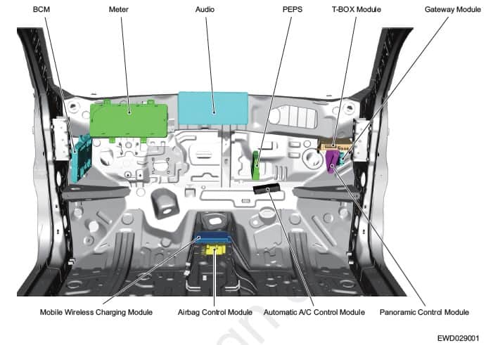
– BCM Terminal Definition
– PEPS Control Module Terminal Definition
– Audio Terminal Definition
– Meter Terminal Definition
– Airbag Control Module Terminal Definition
– Automatic A/C Control Module Terminal Definition
– Mobile Phone Wireless Charging Module Terminal Definition
– Gateway Module Terminal Definition
– Panoramic Control Module Terminal Definition
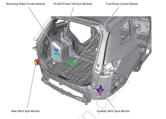
– Reversing Radar Control Module Terminal Definition
– PLGM Module (Power Tail Door Module)
– Fuel Pump Control Module Terminal Definition
– Main Blind Spot Monitor Terminal Definition
– Auxiliary Blind Spot Monitor Terminal Definition
SYSTEM CIRCUITS ELECTRICAL DIAGRAM
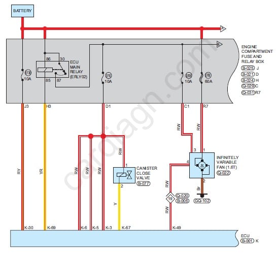
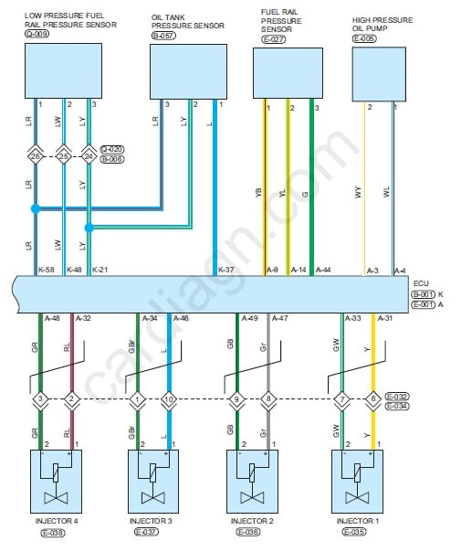
– 1.6TGDI Engine Management System
– 1.6TGDI Fuel Supply System
– 1.6TGDI Emission Control System
– 1.6TGDI Intake System
– 1.6TGDI Exhaust System
– 1.6TGDI Cooling System
– 1.6TGDI Ignition System
– 1.6TGDI Starting System
– 1.6TGDI Charging System
– TCU (7DCT)
– ESP (EPB)
– Electronic Power Steering (EPS)
– Automatic Air Conditioning
– Auto A/C Control Panel
– Supplemental Restraint System
– Passive Entry & Passive Start (PEPS) System
– Lighting System
– Wiper and Washer
– Door Lock
– Meter
– Audio System
– TBOX System
– Multi Function Steering Wheel
– Radar System
– Panoramic Image System
– Blind Spot Monitor System
– Horn
– Other System
– Heating and Defrosting
– Windshield/Window Glass
– Rear View Mirror
– Interior View Mirror
– Seat Adjustment System
– Sunroof
– Power Tail Door (PLG)
– Center Gateway System
– Diagnostic System
– CAN System


Avaliações
Não há avaliações ainda.