CONTENT
GENERAL INFORMATION
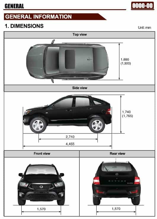
– Dimensions
– Specification
– Vehicle Identification
– Maintenance Interval
– Recommended Fluids and Lubrificants
– Jack-up Points
– Pin Arrangement of Diagnostic connector
ELECTRIC DEVICE GENERAL INFORMATION
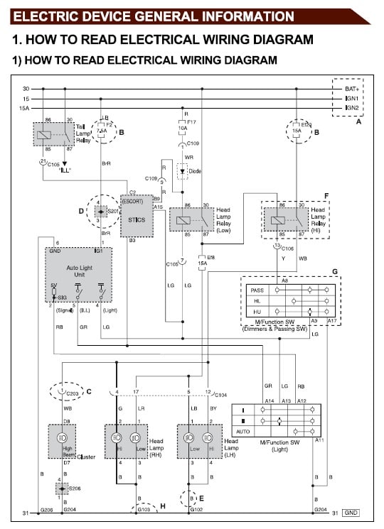
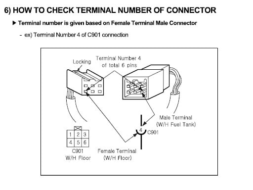
– How to Read Electrical Wiring Diagram
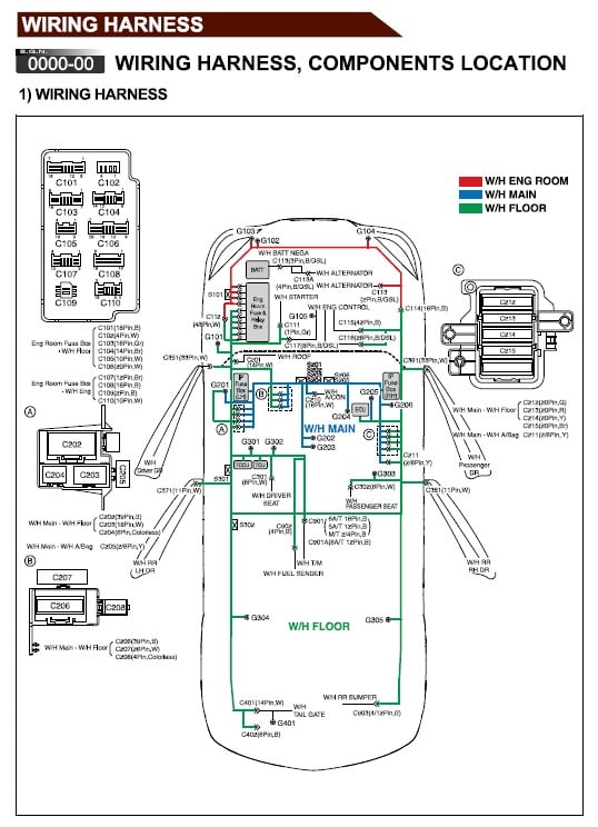
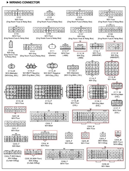
WIRING HARNESS
– Components Location
POWER DISTRIBUTION FUSE / RELAY
– Engine Room Fuse / Relay Box Circuit
– I/P – LH Fuse
– ICM Relay Box Circuit
ENGINE
– Starting / Charging
– Glow Control Unit
– ECU Engine Control Unit (GSL G23)
– Diagnosis Circuit
CHASSIS
– Transmission Control Unit (6-A/T)
– Transmission Control Unit (5-A/T)
– TCCU
– ABS / ESP
ELETRIC
– Air Bag
– Cluster
– Power Seat (Driver)
– Power Seat (Passenger)
– Eletric Outside Mirror
– Front Seat Warmer
– Stics
– Rear Wiper Circuit
– Power Window circuit
– Horn
– Immobilizer Circuit (D20DTR)
– Cigarret Lighter / Power Outlet Circuit
– Sunroof Circuit
– Head Lamp Circuit
– Head Lamp Leveling Device Circuit
– Tail Lamp Circuit
– Turn Signal / Hazard Lamp Circuit
– Trailer Lamp Circuit
– Fog Lamp Circuit
– Stop / Back-up Lamp Circuit
– Interior Lamp Circuit
– Auto Dimming Room Mirror Circuit
– Audio / Clock Circuit
– Parking Aid Circuit
– PTC Heater (Positive Temperature Coefficient)
– FATC (Full Auto Temp. Control) Circuit
– A/C (MANUAL) Circuit
D20DTR ENGINE GENERAL
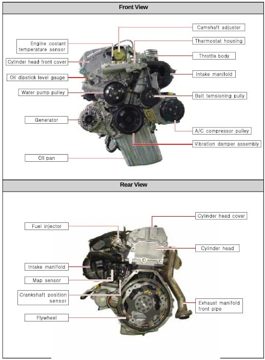
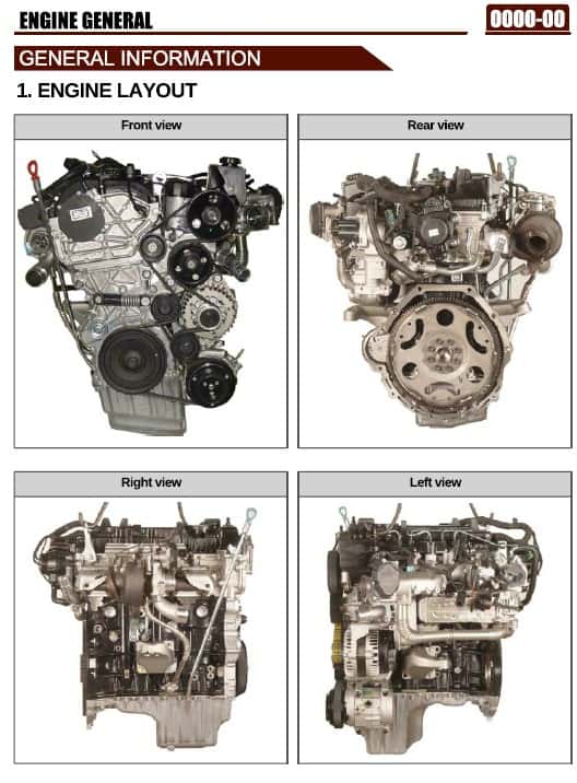
– Engine Layout
– Major Components
– Engine Compartment Layout
– Service Interval
– Standard Bolts Specifications
– Tightening Torque
– Coding and Initialization
ENGINE ASSEMBLY
– Specifications
– Tightening Torque
– Check and Inspection
– Guidelines on Engine Service
– Belt Layout
– Vacuum Pump
– Engine Mounting
– Intake / Exhaust Manifold
– Cylinder Head Cover and Oil Separator
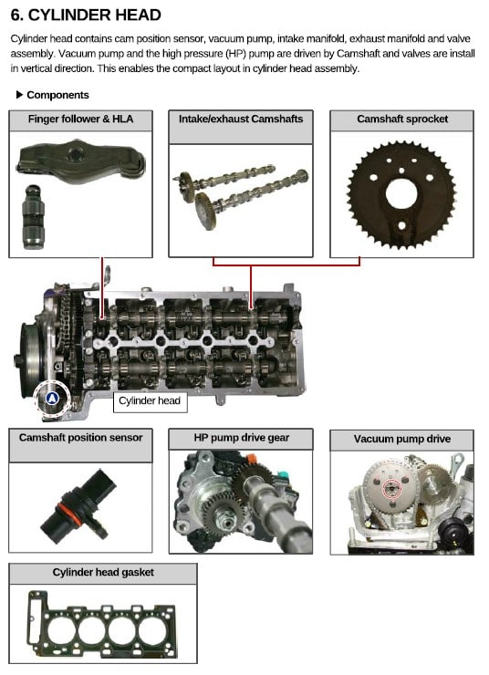
– Cylinder Head
– Chain and Gear Drive System
– Oil Pan
– Dual Mass Flywheel (DMF) & Drive Plate
– Piston / Crankshaft / Cylinder Block
FUEL SYSTEM
– Specification
– Maintenance and Inspection
– Cautions for DI Engine
– Overview
– System Layout and Operation
INTAKE SYSTEM
– Specification
– Inspection
– Overview and Operating Process
– Components
– Input / Output of Intake System
ENGINE EXHAUST SYSTEM
– Thoubleshooting
– Cautions
– Overview
– Layout
– Operating Process
TURBOCHARGER
– Specifications
– Inspection
– Thoubleshooting
– Overview and Operating Process
– System Description of E-VGT (Eletric Variable Geometry Turbine)
– Components
– Input / Output Devices
– Operating Principles
LUBIFICATION SYSTEM
– Specifications
– Maintenance
– System Description
– Functions of Lubrification
COOLING SYSTEM
– Specifications
– Inspection
– Cautions
– System Description
CHARGING SYSTEM
– Specifications
– Inspection
– System Description
– Operating Process
– Circuit Diagram
PRE_HEATING
– Specifications
– Overview
– System Operation
STARTING SYSTEM
– Specifications
– Thoubleshooting
– System Description
– Operating Process
CRUISE CONTROL SYSTEM
– Cruise Control Switch
– How to Operate Cruise Control Switch
E-EGR SYSTEM
– Specification
– System Description
– Overview and Operating Process
CDPF SYSTEM
– Specification
– Cautions
– Overview
– Components
– Input/ Output Devices
– Post Injection and Air Mass Control
– Operating Process
– Electric Circuit Diagram
ENGINE CONTROL
– Engine Data List
– Major Components
– System Operation
– Input/ Output for CAN Communication
G23D ENGINE ASSEMBLY
– Description and Operation
– Engine Assembly
– Engine Structure
– Diagnostic Information and Procedure
– General Diagnosis
– Specifications
FUEL SYSTEM
– Fuel System Specification
– Overview and Operation Process
ENGINE INTAKE SYSTEM
– Specifications
– Description and Operation
LUBRIFICATION SYSTEM
– Oil Circulation
ENGINE COOLING SYSTEM
– General Specification
– Fastener Tightening Specifications
– Overview and Operation Process
– Component Locator
– Description and Operation
– PWM (pulse Width Modulation) Eletric Fan Operation
ENGINE ELETRIC DEVICES
– Diagnostic Information and Procedure
– Overview and Operation
– Description and Operation
CRUISE CONTROL SYSTEM
– Overview and Operation Process
– Cruise Control Switch
– How to Operate Cruise Control Switch
ENGINE CONTROL SYSTEM
– Engine Data Display Table
– Temperature VS Resistance
– Fastener Tightening Specifications
ELETRIC GENERAL
– Locations od Interior Units and Sensors
– Location and Compartment of Interior Switches
– Switches, Units and Sensors in Engine Compartment
– Eletric Components and Layout
– Diagnostic Connector
FUSE AND RELAY
– Cautions When Working on Eletrical Units
– General Information
– Overview
– Fuse & Relay Mounting Location
STICS
– Overview and Operation Process
– Functions and Specifications
– Wiper and Washer Operations
– Wiper MIST and Front Washer Couple Wiper
– Rear Washer Motor Control
– Auto Washer and Wiper Switch (AFW)
– Rain Sensor Coupled Wiper and Auto Ligth Control
– INT Switch Auto Position Reminder (Power-up Reminder Wiper)
– Washer Coupled Wiper in Rain Sensing Mode
– Rain Sensing Sensitivity Control
– When the Wiper Signal is Abnormal
– Defective Rain Sensor
– Auto Ligth Control
– Speed Sensitive INT (Intermittent) Wiper
– Ignition Key Reminder Warning
– All Door Lock Prevention Function When a Door is Open
– Tail Lamp Left on Warning
– Door Ajar Warning
– Seat Belt Warning
– Parking Brake Warning
– Front/ Center Room Lamp Control
– Ignition Key Hole Illumination
– Tail Lamp Auto Cut (Battery Saver)
– Rear Defogger Timer
– Door Lock/ Unlock Control by Door Lock Switch
– Tailgate Open Control
– Door Lock/ Unlock Control by Door Lock Switch
– Door Lock/ Unlock by Remote Control Key
– Auto Door Lock
– Auto Door Unlock
– Time Lag Power Window Control
– Definition of Terms
– Specification of Remote Control Key
– Remote Door Lock
– Door Unlock
– Auto Door Lock in 30 Seconds after Pressing Unlock Button
– Central Door Lock Circuit
– Tail Lamp, Hazard, Power Window Circuit
– Defogger Circuit
– Panic, Auto Ligth, Rain Sensing and Room Lamp Circuit
– Front Wiper, Washer and Rear Washer Circuit
– Mirroe Folding/ Unfolding, Folding SW Circuit
IMMOBILIZER SYSTEM
– Overview and Operation Process
– Basic Function of Immobilizer Key (Rekes Function)
– Other Function in System
– Rekes Operation Logic
– Circuit Diagram
CLUSTER
– Specification
– Overview and Operating Process
– Description of Indicator Display
– Configuration
– Warning Ligths and Indicators
– Self-Diagnosis Check
– Buzzer Output SPEC
– Circuit Diagram
– Warning Lamp (BATT Charge, Oil, Hood, Door, ENG Check, Air Bag, Seat Belt), Fog Lamp, Hazard Circuit
LAMP
– Specification
SWITCH
– Switch Arrangement
WIPER & WASHER SYSTEM
– System Layout and Function
– Configuration (Including Rain Sensor)
– Wiper & Washer Related Function and Specification
– Wiper and Washer System Related Circuit Diagram
RAIN SENSOR
– Overview and Operation Process
– System Layout and Overview
– Rain Sensing Operation
– Rain Sensor Related Circuit
– Functions and Specifications of Rain Sensing Wiper
– Operation Mode of Rain Sensing Wiper System
PARKING AID SYSTEM
– Component Specification
– Cautions on Parking Aid System
– Overview and Operation Process
– System Overview
– Alarm Interval
– Troubleshooting of Sensor
– Circuit Diagram
AUDIO SYSTEM
– Overview and Installation
– Audio System Overview
MB5 AUTOMATIC TRANSMISSION
– Specification
– Tightening Torque
– Overview and Operation Process
– Power Flow
– Circuit Diagram
DSI6 AUTOMATIC TRANSMISSION
– General Information
– Features and Specifications
– Tightening Torque
– Shift Pattern Diagram
– Overview and Operation Process
– Mode Description
– Limp Home Mode
– Electronic Control System
– Power Flow
MANUAL TRANSMISSION (5 M/T)
– Overview and Characteristics of Manual Transmission
– Specifications and Tightening Torque of Manual Transmission
– Overview and Operation Process
– Manual Transmission System
MANUAL TRANSMISSION (6 M/T)
– Specification
– Special Service Tools
– Tightening Torque
– Overview and Operation Process
– Power Flow
– Shifting Mechanism
TGS LEVER
– Introduction
– Function of The Selector Lever
– Mode Switch
– Parking Lock System
CLUTCH
– Clutch Specifications
– Tightening Torque
– Overview and Operation Process
– Function and Overview
PROPELLER SHAFT
– Specification
– Tightening Torque
– Overview and Operation Process
AXLE
– Specification of Axle
– Overview and Operation Process
– Overview of Axle
TRANSFER CASE
– Overview
– Specifications
– Structure
– System Layout and Operation
– Locking HUB System
– Power Flow
SUSPENSION
– Specifications of Suspension
– Wheel Alignment
BRAKE SYSTEM
– Specification
– System Overview
– Troubleshooting
– Air Bleeding
– Brake System Check
– Components
– Overview and Operation Process
– Overview
– System Layout
– Parking Brake
– Hydraulic Circuit
– Circuit Diagram of Stop Lamp
ABS (Anti-Block System) & HDC (Hill Descent Control) & EPS (Electric Stability Program) & BAS (Brake Assist System) & ARP (Active Roll-Over Protection)
– System General
– Sectional Drawing
– Specifications
– Brake Operation and Noise
– ESP System Related Precautions
– Overview and Operation Process
– Overview of ESP System
– Components of ESP
– Principle of ESP
– Principle of BAS
– Principle of ARP
– Principle of HDC
– Imput and Output Diagram of ESP System
– Hydraulic Circuit Diagram of ESP System
– Hydraulic Pressure for Each ESP Operating Range
– Hydraulic Circuit of BAS
– Components of ABS System
STEERING
– Overview
– Specifications
– System Layout
– Components
WHEEL TIRE
– Specifications
– Trouble Diagnosis
– Inspection
– Components
– Overview and Operation Process
– Overview
– Abnormal Tire Symptom
– Wheel Balance
AIR CONDITIONER
– Overview and Operation Process
– System Layout and Components
– Ventilation System
– Air Conditioner Module and Sensors
– System Diagram
AIR BAG
– Overview (Including Curtain Bags)
– Locations and Related Components
– Air Bag System Operation Process
– Air Bag Module and Related Components
– Eletrical Wire Diagram
SEAT
– Overview and Operation Process
– Composition of Seat
– Functions of Seat
– Components of Seat Belt
– Circuit Diagram
SUNROOF
– Overview and Operation Process
– Components and Locations
– Operation and Function
– Circuit Diagram
BODY INTERIOR
– Overview and Operation Process
– Locations
BODY EXTERIOR
– Overview and Operation Process
– Composition of Body Exterior
BODY REPAIR
– Dimensions
– Jack-up Points
– Design Changes for Improving NVH Performance


Avaliações
Não há avaliações ainda.