Content:
4-cylinder common rail (1.6 l and 2.0 l, 4 V, turbocharger, EA 288) – Engine ID: DCY A, DDM A, DFG A, DFG B, CRF C, CYK B, DFH A, DCY B, DGD B, DBG A, CRG A, DFG C, CYK C, DBG C, CRG B, CRF Z, CRF D, DGT E, DFFA, DGT C, DGT D
Technical data:
1 Safety information
1.1 Safety regulations for working on fuel supply
1.2 Safety measures when working on vehicles with a start/stop system
1.3 Safety precautions when using testers and measuring instruments during a road test
1.4 Safety precautions when working on the cooling system
1.5 Safety precautions when working on the SCR system
1.6 Safety precautions when working on exhaust system
2 Identification
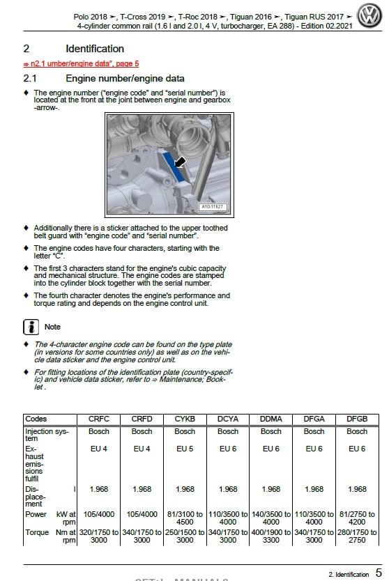
2.1 Engine number/engine data
3 Repair instructions
3.1 Rules for cleanliness
3.2 Foreign objects in engine
3.3 Contact corrosion
3.4 Routing and attachment of lines
3.5 Fitting radiator and condensers
4 Technical data
4.1 Coolant
Removing and installing engine:
1 Removing and installing engine
1.1 Removing engine
1.2 Separating engine and gearbox
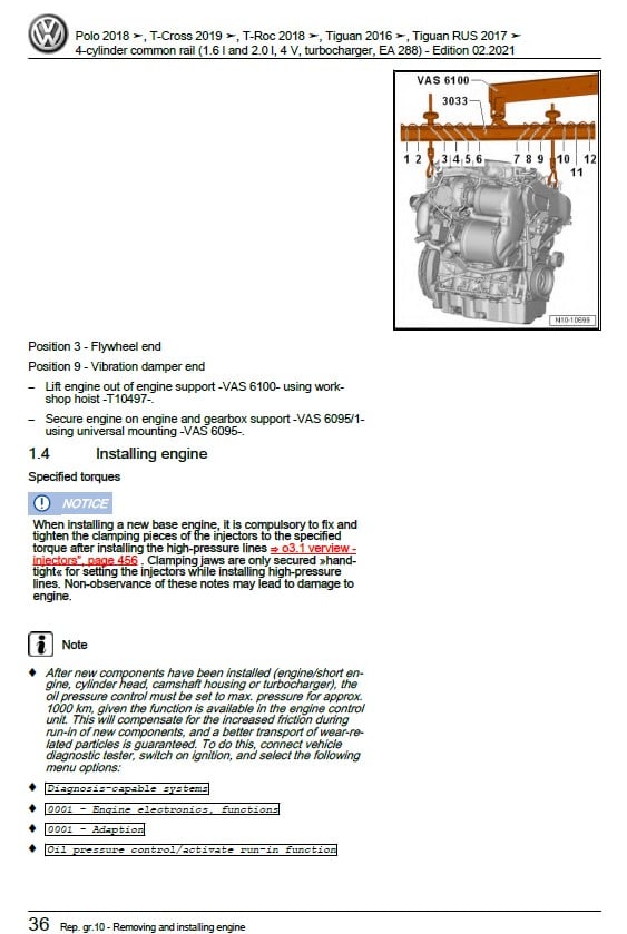
1.3 Securing engine on engine and gearbox support
1.4 Installing engine
2 Assembly mountings
2.1 Assembly overview – assembly mountings
2.2 Removing and installing engine mounting
2.3 Removing and installing gearbox mounting
2.4 Removing and installing pendulum support
2.5 Supporting engine in installation position
2.6 Adjusting assembly mountings
2.7 Checking adjustment of assembly mountings
3 Engine cover panel
3.1 Removing and installing engine cover
Crankshaft group:
1 Cylinder block (pulley end)
1.1 Assembly overview – cylinder block (pulley end)
1.2 Assembly overview – sealing flange, belt pulley end
1.3 Removing and installing poly-V belt
1.4 Removing and installing tensioner for poly V-belt
1.5 Removing and installing vibration damper
1.6 Removing and installing bracket for ancillaries
1.7 Removing and installing engine support
1.8 Removing and installing sealing flange on pulley end
1.9 Renewing caps in cylinder block (pulley end)
2 Cylinder block, gearbox end
2.1 Assembly overview – cylinder block, gearbox end
2.2 Removing and installing flywheel
2.3 Removing and installing sealing flange on gearbox side
2.4 Renewing caps in cylinder block (gearbox end)
Crankshaft:
3.1 Assembly overview – crankshaft
3.2 Crankshaft dimensions
3.3 Measuring axial clearance of crankshaft
3.4 Renewing needle bearing in crankshaft
4 Pistons and conrods
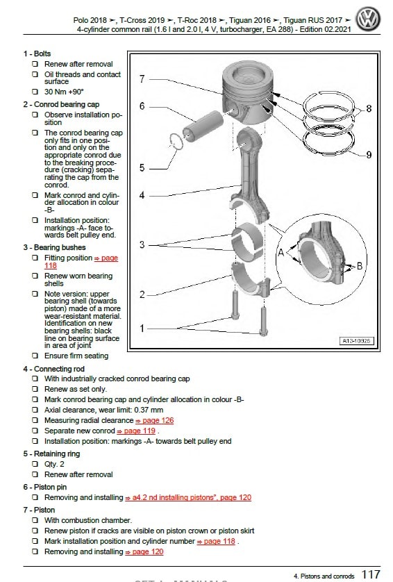
4.1 Assembly overview – pistons and conrods
4.2 Removing and installing pistons
4.3 Measuring piston projection at TDC
4.4 Checking pistons and cylinder bores
4.5 Checking radial clearance of conrods
Cylinder head, valve gear:
1 Cylinder head
1.1 Assembly overview – cylinder head
1.2 Assembly overview – cylinder head cover
1.3 Removing and installing cylinder head
1.4 Removing and installing cylinder head cover
1.5 Removing and installing injector seals
1.6 Removing and installing camshaft housing
1.7 Checking compression
2 Toothed belt drive
2.1 Assembly overview – toothed belt cover
2.2 Assembly overview – toothed belt
2.3 Removing and installing toothed belt guard
2.4 Removing and installing toothed belt
2.5 Removing toothed belt from camshaft
Valve gear:
3.1 Assembly overview – valve gear
3.2 Measuring axial play of camshaft
3.3 Removing and installing camshaft oil seal
3.4 Removing and installing camshaft adjuster
3.5 Removing and installing camshaft control valve 1 N205
3.6 Checking hydraulic compensation elements
3.7 Removing and installing valve stem seals
3.8 Removing and installing control valve for the camshaft adjuster
Inlet and exhaust valves:
4.1 Checking valve guides
4.2 Checking valves
4.3 Valve dimensions
Lubrication:
1 Sump, oil pump
1.1 Assembly overview – sump/oil pump
1.2 Engine oil
1.3 Removing and installing sump
1.4 Removing and installing lower part of sump
1.5 Removing and installing upper part of sump
1.6 Removing and installing oil pump
1.7 Removing and installing oil level and oil temperature sender G266
Engine oil cooler:
3 Oil filter, oil pressure switch
3.1 Assembly overview – oil filter housing, oil pressure switch
3.2 Removing and installing oil pressure switch F1
3.3 Removing and installing oil pressure switch for reduced oil pressure F378
3.4 Checking oil pressure
3.5 Removing and installing oil filter housing
3.6 Removing and installing oil pressure regulating valve N428
Oil circuit:
4.1 Removing and installing oil supply line
4.2 Removing and installing oil return line for turbocharger
Cooling:
1 Cooling system/coolant
1.1 Connection diagram – coolant hoses
1.2 Checking cooling system for leaks
1.3 Draining coolant
1.4 Filling with coolant
1.5 Checking filling quality of cooling system
1.6 Checking electric vacuum pump VAS 6096/2
1.7 Flushing cooling system
2 Coolant pump, regulation of cooling system
2.1 Assembly overview – coolant pump, thermostat
2.2 Assembly overview – electric coolant pump
2.3 Assembly overview – coolant temperature sender
2.4 Removing and installing electric coolant pump
2.5 Removing and installing coolant pump
2.6 Removing and installing thermostat
2.7 Checking thermostat
2.8 Removing and installing coolant valve for cylinder head N489
2.9 Removing and installing coolant temperature sender G62
2.10 Removing and installing radiator outlet coolant temperature sender G83
Coolant pipe:
3.1 Assembly overview – coolant pipes
3.2 Removing and installing coolant pipes
Radiator, radiator fan:
4.1 Assembly overview – radiator/radiator fan
4.2 Assembly overview – radiator cowl and radiator fan
4.3 Removing and installing radiator
4.4 Removing and installing water radiator for charge air cooling circuit
4.5 Removing and installing radiator cowl
4.6 Removing and installing radiator fan
Turbocharging/supercharging:
1 Turbocharger
1.1 Assembly overview – turbocharger
1.2 Removing and installing turbocharger
1.3 Renewing vacuum unit for turbocharger
1.4 Removing and installing connection for turbocharger
Charge air system:
2.1 Assembly overview – charge air system
2.2 Removing and installing charge pressure sender G31
2.3 Checking charge air system for leaks
2.4 Removing and installing air pipe
2.5 Checking charge air cooler for leaks
Mixture preparation – injection:
1 Injection system
1.1 Schematic overview – fuel system
1.2 Overview of fitting locations – injection system
1.3 Filling/bleeding fuel system
1.4 Checking fuel system for leaks
2 Vacuum system
2.1 Connection diagram – vacuum system
2.2 Checking vacuum system
Injectors/high-pressure accumulator (rail):
3.1 Assembly overview – injectors
3.2 Assembly overview – fuel rail
3.3 Adapting correction values for injectors
3.4 Testing injectors
3.5 Checking return flow rate of injectors with engine running
3.6 Checking return flow rate of injectors at starter speed
3.7 Testing jammed-open injectors
3.8 Removing and installing injectors
3.9 Removing and installing high-pressure lines
3.10 Removing and installing fuel rail
Air filter:
4.1 Assembly overview – air filter housing
4.2 Removing and installing air filter housing
4.3 Removing and installing air guide on lock carrier
Intake manifold:
5.1 Assembly overview – intake manifold
5.2 Removing and installing intake manifold
5.3 Removing and installing throttle valve module J338
Senders and sensors:
6.1 Removing and installing fuel pressure regulating valve N276
6.2 Checking fuel pressure regulating valve N276
6.3 Removing and installing fuel pressure sender G247
6.4 Removing and installing air mass meter G70/intake air temperature sender G42
6.5 Removing and installing pressure differential sender G505
6.6 Removing and installing exhaust gas pressure sensor 1 G450
6.7 Removing and installing NOx sender 2 G687
6.8 Removing and installing charge air temperature sender ahead of charge air cooler G810
6.9 Removing and installing charge air temperature sender after charge air cooler G811
6.10 Removing and installing fuel temperature sender G81
6.11 Removing and installing control unit for NOx sender GX30
6.12 Removing and installing temperature and pressure sender for low-pressure fuel system
GX20
Engine/motor control unit:
7.1 Removing and installing engine control unit J623
7.2 Removing and installing engine control unit J623 (with protective housing)
8 High-pressure pump
8.1 Assembly overview – high-pressure pump
8.2 Removing and installing high-pressure pump
Lambda probe:
9.1 Assembly overview – Lambda probe
9.2 Removing and installing Lambda probe
Exhaust system:
1 Exhaust pipes and silencers
1.1 Assembly overview – silencers
1.2 Assembly overview – front exhaust pipe
1.3 Removing and installing front exhaust pipe
1.4 Separating exhaust pipes from silencers
1.5 Removing and installing silencer
1.6 Aligning exhaust system free of stress
1.7 Checking exhaust system for leaks
1.8 Installation position of clamp
1.9 Align end exhaust pipes
1.10 Removing and installing bracket for front exhaust pipe
Emission control:
2.1 Assembly overview – emission control
2.2 Removing and installing catalytic converter
2.3 Removing and installing particulate filter
2.4 Removing and installing emission control module
2.5 Removing and installing exhaust flap control unit J883
SCR system (selective catalytic reduction):
3.1 Assembly overview – tank for reducing agent
3.2 Assembly overview – reducing agent supply line
3.3 Assembly overview – delivery module for reducing agent
3.4 Assembly overview – filler tube for reducing agent tank
3.5 Removing and installing reducing agent tank
3.6 Removing and installing front section of reducing agent supply line
3.7 Removing and installing delivery module for reducing agent
3.8 Removing and installing injector for reduction agent N474
3.9 Removing and installing control unit for reducing-agent heater J891
3.10 Assembly overview – injector for reducing agent
3.11 Draining reducing agent tank
3.12 Removing and installing rear section of reducing agent supply line
3.13 Removing and installing filler pipe for reducing agent tank
3.14 Disconnecting reducing agent supply line
3.15 SCR – resetting learnt values
Exhaust gas temperature regulation:
4.1 Assembly overview – exhaust gas temperature regulation
4.2 Removing and installing exhaust gas temperature sender 1 G235
4.3 Removing and installing exhaust gas temperature sender 2 G448
4.4 Removing and installing exhaust gas temperature sender 3 G495
4.5 Removing and installing exhaust gas temperature sender 4 G648
Exhaust gas recirculation:
5.1 Assembly overview – exhaust gas recirculation
5.2 Assembly overview – exhaust gas recirculation valve 1 GX5
5.3 Removing and installing exhaust gas recirculation cooler
5.4 Removing and installing exhaust gas recirculation valve 1 GX5
5.5 Removing and installing exhaust gas recirculation valve 2 GX6
5.6 Removing and installing exhaust gas recirculation temperature sensor G98
5.7 Checking exhaust gas recirculation cooler for leaks
Glow plug system:
1 Glow plug system
1.1 Assembly overview – glow plug system
1.2 Removing and installing glow plug
1.3 Removing and installing automatic glow period control unit J179
1.4 Removing and installing Hall sender G40
1.5 Removing and installing engine speed sender G28
Brake system
Technical data:
1 Safety information
1.1 Safety precautions when using testers and measuring instruments during a road test
Identification:
2.1 Allocation of PR number – brakes
Technical data:
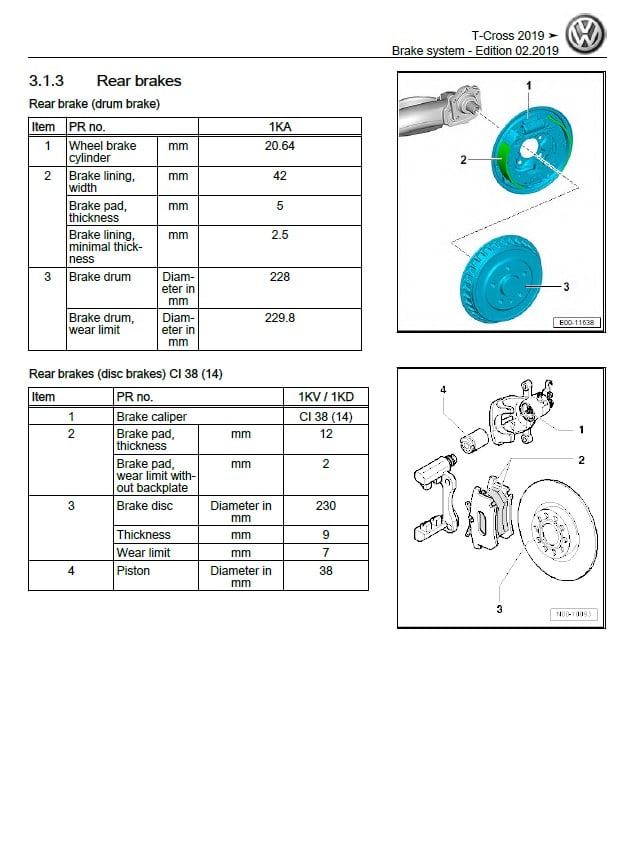
3.1 Technical data for brakes
Brake test:
4.1 General information
4.2 Checking vehicles with front-wheel drive
Anti-lock brake system:
1 General information
1.1 Repair instructions for repair work on ABS
Overview of fitting locations:
2.1 Overview of fitting locations – ABS/ESP
Control unit and hydraulic unit:
3.1 Assembly overview – control unit and hydraulic unit
3.2 Removing and installing ABS control unit J104 and ABS hydraulic unit N55
3.3 Separating control unit from hydraulic unit
3.4 Fitting control unit to hydraulic unit
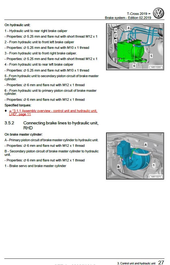
3.5 Connecting brake lines to hydraulic unit
Sensors:
4.1 Assembly overview – speed sensor on front axle
4.2 Assembly overview – speed sensor on rear axle
4.3 Removing and installing speed sensors on front axle G45 / G47
4.4 Removing and installing speed sensors on rear axle G44 / G46
4.5 Checking ABS sensor ring
Brakes – mechanism :
1 Front brakes
1.1 Assembly overview – front brakes
1.2 Removing and installing brake pads/linings
1.3 Removing and installing brake caliper
1.4 Removing and installing brake disc
1.5 Removing and installing brake splash plate
Rear brakes:
2.1 Assembly overview – rear brakes
2.2 Removing and installing brake pads/linings
2.3 Removing and installing brake caliper
2.4 Removing and installing brake carrier
2.5 Removing and installing brake disc
2.6 Removing and installing brake shoes
2.7 Resetting drum brakes
2.8 Removing and installing brake splash plate
Parking brake:
3.1 Assembly overview – parking brake
3.2 Removing and installing handbrake lever
3.3 Removing and installing handbrake warning switch F9
3.4 Adjusting parking brake
3.5 Removing and installing rear brake cable
Brake pedal:
4.1 Assembly overview – brake pedal
4.2 Separating brake pedal from brake servo
4.3 Connecting brake pedal to brake servo
4.4 Removing and installing mounting bracket
4.5 Removing and installing brake pedal
Brakes – hydraulics:
1 Front brake caliper
1.1 Assembly overview – front brake caliper
1.2 Removing and installing brake caliper piston
2 Rear brake caliper
2.1 Assembly overview – rear brake caliper
2.2 Removing and installing brake caliper piston
Brake servo and brake master cylinder:
3.1 Assembly overview – brake servo/brake master cylinder
3.2 Removing and installing brake light switch
3.3 Removing and installing brake servo
3.4 Removing and installing brake master cylinder
3.5 Removing and installing brake fluid reservoir
Vacuum system:
4.1 Assembly overview – vacuum pump
4.2 Checking non-return valve
4.3 Removing and installing vacuum sender G608
4.4 Checking vacuum system
4.5 Removing and installing electric vacuum pump
Brake lines:
5.1 Repairing brake lines
Hydraulic system:
6.1 General notes on brake fluid
6.2 Bleeding hydraulic system following standard procedure
6.3 Subsequent bleeding of hydraulic system
6.4 Leakage test
Communication
Technical data:
1 Repair instructions
1.1 General repair instructions
1.2 Routing and attachment of lines
1.3 Notes on repair of CAN bus wiring
1.4 General information
Communication:
1 Infotainment system
1.1 Layout – infotainment system
1.2 Overview of fitting locations – Infotainment system
1.3 Removing and installing infotainment system display
1.4 Removing and installing control unit 1 for information electronics J794
1.5 Removing and installing CD player R89
1.6 Renewing rotary knobs of display unit for front information display and operating unit control
unit J685
Sound system:
2.1 Components of sound system
2.2 Overview of fitting locations – sound system
2.3 Removing and installing digital sound package control unit/amplifier
2.4 Removing and installing retainer for digital sound package control unit J525
2.5 Removing and installing front treble loudspeakers R20 / R22
2.6 Removing and installing rear loudspeaker R4 / R5
2.7 Removing and installing front bass loudspeakers R21 / R23
2.8 Removing and installing subwoofer R211
2.9 Removing and installing subwoofer R211
Aerial systems:
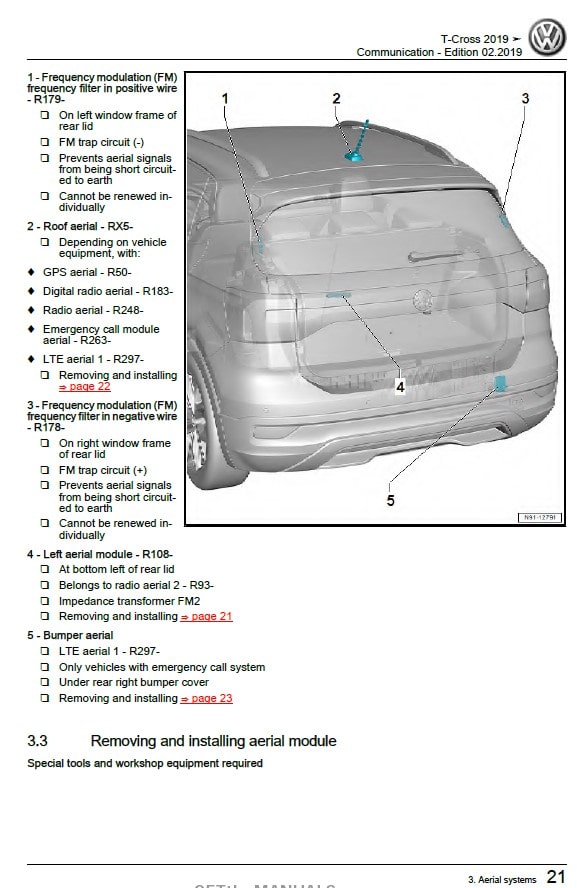
3.1 Components of aerial systems
3.2 Overview of fitting locations – aerial systems
3.3 Removing and installing aerial module
3.4 Removing and installing roof aerial
3.5 Removing and installing bumper aerial
Radio:
4.1 Components of radio system
4.2 Removing and installing radio
5 Telephone system
5.1 Mobile telephone preparation
5.2 Overview of fitting locations – telephone system
5.3 Removing and installing telephone microphone R38
5.4 Removing and installing two-way signal amplifier for mobile telephone/data services J984
5.5 Removing and installing storage compartment with interface for mobile telephone R265
Navigation system:
6.1 Components of navigation system
6.2 Overview of fitting locations – navigation system
6.3 Removing and installing control unit for navigation system
Reversing camera system:
8 Multifunction steering wheel
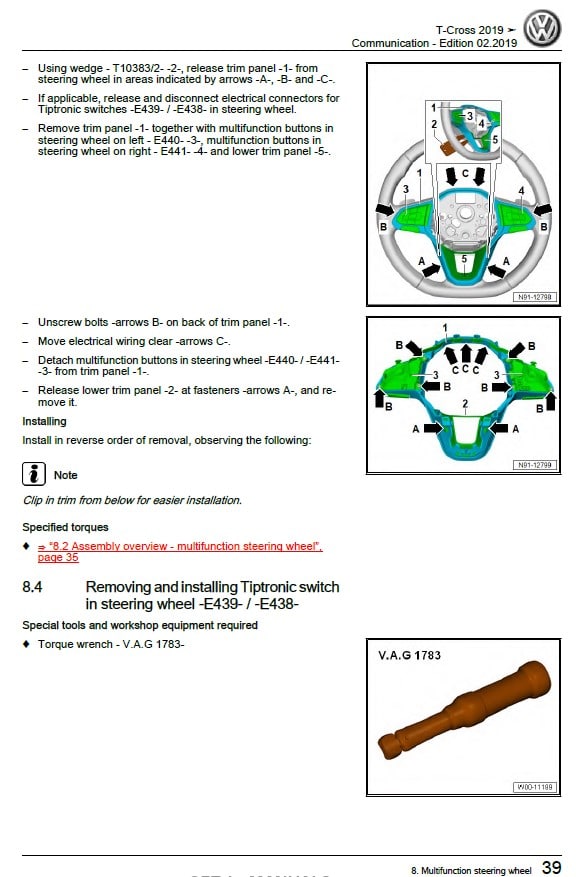
8.1 Components of multifunction steering wheel
8.2 Assembly overview – multifunction steering wheel
8.3 Removing and installing steering wheel multifunction buttons E441 / E440
8.4 Removing and installing Tiptronic switch in steering wheel E439 / E438
Connection for external multimedia devices:
9.1 Removing and installing connection for external multimedia devices
9.2 Removing and installing USB hub R293
9.3 Removing and installing USB charging socket 1 U37
Car-Net:
10.1 General description – Car-Net services
10.2 Overview of fitting locations – Car-Net services
10.3 Removing and installing emergency call module control unit and communication unit J949
10.4 Removing and installing telematics button module E734
10.5 Removing and installing loudspeaker for emergency call module R335
10.6 Removing and installing battery for emergency call module control unit and communication
unit J949
10.7 Renewing control unit for emergency call module and communication unit J949
1.0l petrol engine , DKJA,DKLA,DKRF – Wiring Diagram Current Flow Diagram
Electrical system
Technical data:
1 Safety information
1.1 Safety measures when working on vehicles with a start/stop system
1.2 Safety precautions when using testing and measuring instruments during a road test
Repair instructions:
2.1 Rules for cleanliness
2.2 General information
2.3 Contact corrosion
2.4 Routing and attachment of lines
Battery:
3.1 Battery – general notes
3.2 Types of battery
Starter, current supply, CCS, Battery:
1.1 Assembly overview – battery
1.2 Removing and installing battery
1.3 Disconnecting and connecting battery
1.4 Removing and installing battery tray
1.5 Checking battery
1.6 Charging battery
1.7 Removing and installing earth wire with battery monitor control unit J367
1.8 Adapting battery monitor control unit J367
Alternator:
2.1 Assembly overview – alternator
2.2 Removing and installing alternator
2.3 Checking alternator
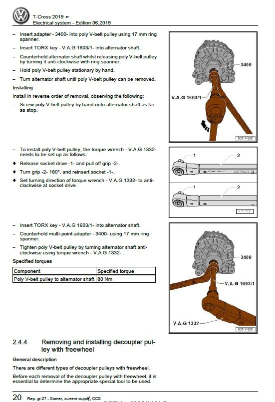
2.4 Removing and installing poly V-belt pulley
2.5 Removing and installing voltage regulator
Starter motor:
3.1 Assembly overview – starter
3.2 Removing and installing starter
3.3 Checking starter
Cruise control system (CCS):
5 Adaptive cruise control
Gauges, instruments:
1 Dash panel insert
1.1 Assembly overview – dash panel insert
1.2 Removing and installing dash panel insert KX2
Horn:
2.1 Assembly overview – horn
2.2 Removing and installing treble horn H2 and bass horn H7
Windscreen wash/wipe system:
1 windscreen wiper system
1.1 Assembly overview – windscreen wiper system
1.2 Moving wipers to service position
1.3 Removing and installing wiper blade
1.4 Removing and installing wiper arms
1.5 Adjusting wiper arms
1.6 Removing and installing wiper motor V
1.7 Deactivating APP function of wiper motor
1.8 Removing and installing rain and light sensor
Windscreen washer system:
2.1 Assembly overview – windscreen washer system
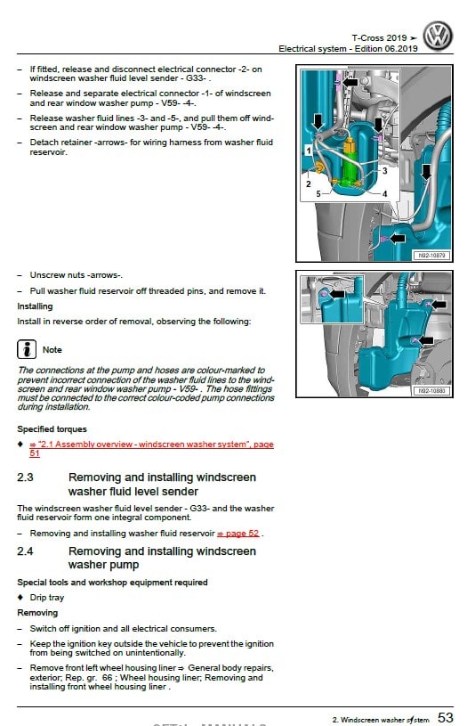
2.2 Removing and installing washer fluid reservoir
2.3 Removing and installing windscreen washer fluid level sender
2.4 Removing and installing windscreen washer pump
2.5 Removing and installing washer jets
2.6 Adjusting spray jets
Rear window wiper system:
3.1 Assembly overview – rear window wiper system
3.2 Removing and installing wiper blade
3.3 Removing and installing wiper arm
3.4 Adjusting wiper arm
3.5 Removing and installing rear window wiper motor V12
Rear window washer system:
4.1 Assembly overview – rear window washer system
4.2 Removing and installing washer fluid reservoir
4.3 Removing and installing rear window washer pump
4.4 Removing and installing spray jet
4.5 Adjusting spray jet
5 Washer fluid lines
5.1 Repairing washer fluid lines
Lights, bulbs, switches – exterior:
Headlights
1.1 Assembly overview – headlight
1.2 Removing and installing headlight
1.3 Adjusting headlights
1.4 Adjusting headlight installation position
1.5 Removing and installing front turn signal bulb M5 / M7
1.6 Installing repair kit for headlight housing
1.7 Converting headlights from driving on right to driving on left
1.8 Converting headlights from driving on left to driving on right
1.9 Removing and installing headlight range control motor V48 / V49
1.10 Removing and installing dipped beam bulb
1.11 Removing and installing headlight main beam bulb M30 / M32
1.12 Removing and installing daytime running light
1.13 Removing and installing LED modules for daytime running light and side light L176 / L177
1.14 Removing and installing bulbs for cornering light L148 / L149
1.15 Removing and installing output module 1 for LED headlight A31 / A27
Fog lights:
2.1 Assembly overview – fog lights
2.2 Removing and installing fog light
2.3 Removing and installing fog light bulb L22 / L23
2.4 Adjusting fog lights
Lights in exterior mirror:
3.1 Assembly overview – lights in exterior mirror
3.2 Removing and installing turn signal
Tail lights:
4.1 Assembly overview – tail lights in body
4.2 Removing and installing bulb carrier
4.3 Removing and installing tail light cluster
4.4 Adjusting installation position of tail light
4.5 Removing and installing tail light bulb M2 / M4
4.6 Removing and installing rear fog light
4.7 Removing and installing rear fog light bulb L46 / L47
4.8 Removing and installing brake and tail light bulb M21 / M22
4.9 Removing and installing reversing light bulb
4.10 Removing and installing turn signal bulb
High-level brake light:
5.1 Assembly overview – high-level brake light
5.2 Removing and installing high-level brake light
Number plate light:
6.1 Removing and installing number plate light X4 / X5
6.2 Removing and installing bulb for number plate light X4 / X5
Entry and start authorization system:
7.1 Overview of fitting locations – entry and start authorization system
7.2 Overview of fitting locations – keyless entry system
7.3 Removing and installing entry and start authorization control unit J518
7.4 Removing and installing contact sensor for front left exterior door handle G605 / G606
7.5 Removing and installing interior aerial 1 for entry and start system R138
7.6 Removing and installing interior aerial 2 for entry and start system R139
7.7 Removing and installing left entry and start authorization aerial R200
7.8 Removing and installing right entry and start authorization aerial R201
7.9 Removing and installing rear bumper aerial for entry and start system R136
Steering column switch module:
8.1 Assembly overview – steering column switch module
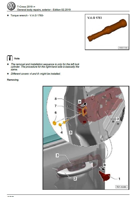
8.2 Removing and installing lock cylinder
8.3 Removing and installing ignition key withdrawal lock solenoid N376
8.4 Removing and installing ignition/starter switch
8.5 Removing and installing steering column switch module
8.6 Removing and installing steering column electronics control unit J527
8.7 Removing and installing turn signal switch E2
8.8 Removing and installing cruise control system switch E45
8.9 Removing and installing intermittent wiper switch E22
8.10 Removing and installing base for steering column combination switch
8.11 Removing and installing steering lock housing
Parking aid:
10 Park assist steering
11 Automatic headlight range control
11.1 Assembly overview – automatic headlight range control
11.2 Removing and installing headlight range control unit
12 Blind Spot Monitor
Lights, bulbs, switches – interior Lights
1.1 Overview of fitting locations – lights in dash panel
1.2 Overview of fitting locations – lights in front doors
1.3 Overview of fitting locations – lights in centre console
1.4 Overview of fitting locations – lights in luggage compartment
1.5 Overview of fitting locations – lights in roof trim
1.6 Removing and installing glove compartment light W6
1.7 Replacing bulb for glove compartment light W6
1.8 Removing and installing front footwell light K268 / K269
1.9 Removing and installing front footwell illumination bulb L151 / L152
1.10 Removing and installing Central locking SAFELOCK function warning lamp K133
1.11 Removing and installing storage compartment illumination bulb L120
1.12 Removing and installing interior door handle illumination bulb L146 / L147
1.13 Removing and installing light for left dashboard ambient lighting L229
1.14 Removing and installing light for right dashboard ambient lighting L230
1.15 Removing and installing light for centre dashboard ambient lighting L231
1.16 Removing and installing selector lever position display Y26
1.17 Removing and installing luggage compartment light W3
1.18 Removing and installing bulb for luggage compartment light W3
1.19 Renewing front interior light bulb W1 / W13 / W19
1.20 Renewing bulb for rear interior light W43
1.21 Removing and installing bulb for rear reading light W11 / W12
Controls:
2.1 Overview of fitting locations – controls in dash panel
2.2 Overview of fitting locations – controls in front doors
2.3 Overview of fitting locations – controls in rear doors
2.4 Overview of fitting locations – controls in centre console
2.5 Overview of fitting locations – controls in luggage compartment
2.6 Overview of fitting locations – controls in roof trim
2.7 Removing and installing rotary light switch EX1
2.8 Removing and installing headlight range control regulator E102
2.9 Removing and installing parking aid button E266
2.10 Removing and installing park assist steering button E581
2.11 Removing and installing Start/Stop operation button E693
2.12 Removing and installing button for Charisma E735
2.13 Removing and installing front passenger side airbag deactivated warning lamp K145
2.14 Removing and installing switch module in centre console
2.15 Removing and installing hazard warning light switch EX3
2.16 Removing and installing buttons for seat heating E653 / E654
2.17 Removing and installing glove compartment light switch E26
2.18 Removing and installing exterior mirror adjuster EX11
2.19 Removing and installing operating unit for window regulator in driver door E512
2.20 Removing and installing window regulator switch in front passenger door EX27
2.21 Removing and installing driver side interior locking button for central locking system E308
2.22 Removing and installing door contact switch F2 / F3
2.23 Removing and installing rear window regulator switch in door E52 / E54
2.24 Removing and installing rear door contact switches F10 / F11
2.25 Removing and installing the starter button E378
2.26 Removing and installing rear lid contact switch
2.27 Removing and installing front interior light/reading light
2.28 Removing and installing rear interior light/reading light
Anti-theft alarm:
3.1 Assembly overview – interior monitor
3.2 Removing and installing anti-theft alarm H8
3.3 Removing and installing anti-theft alarm sensor G578
Immobilizer:
4.1 Removing and installing immobilizer control unit
4.2 Removing and installing immobilizer reader coil
Towing bracket:
5.1 Assembly overview – socket, trailer detector control unit
5.2 Trailer socket
5.3 Removing and installing trailer detector control unit J345
Cigarette lighter, socket:
6.1 Removing and installing cigarette lighter U1
6.2 Removing and installing socket illumination bulb L42
6.3 Removing and installing rear cigarette lighter illumination bulb L32
6.4 Removing and installing electric socket U
Wiring:
1 Relay carriers, fuse holders, electronics boxes
1.1 Overview of fitting locations – relay carriers, fuse holders, E-boxes
1.2 Assembly overview – fuse holder A SA
1.3 Removing and installing electronics box (E-box)
1.4 Removing and installing relay and fuse holder in electronics box
1.5 Removing and installing relay and fuse holder behind dash panel on driver side
1.6 Removing and installing fuse holder A SA
Control units:
2.1 Overview of fitting locations – control units
2.2 Removing and installing onboard supply control unit J519
2.3 Removing and installing data bus diagnostic interface J533
2.4 Removing and installing bracket for onboard supply control unit J519
Connectors:
3.1 Repairing electrical wiring harnesses and plug-in connections
4 Releasing and dismantling connector housings
5 Repairing aerial wires
6 Fibre optic cables
7 Vehicle diagnosis, testing and information systems
General body repairs, exterior
Technical data:
1 Safety information
1.1 Safety measures when working on vehicles with a start/stop system
Body front:
1 Lock carrier
1.1 Assembly overview – lock carrier
1.2 Removing and installing lock carrier
1.3 Moving to and back from service position Wings
2.1 Assembly overview – wing
2.2 Removing and installing wing
3 Bulkhead
3.1 Assembly overview – plenum chamber bulkhead
3.2 Assembly overview – plenum chamber cover
3.3 Removing and installing plenum chamber bulkhead
3.4 Removing and installing plenum chamber cover
Bonnet, rear lid:
1 Bonnet (hood)
1.1 Assembly overview – bonnet
1.2 Assembly overview – Bowden cable
1.3 Removing and installing bonnet
1.4 Adjusting bonnet
1.5 Removing and installing bonnet lock
1.6 Removing and installing bonnet release lever
1.7 Removing and installing striker pin
1.8 Removing and installing hinges
1.9 Removing and installing insulation
1.10 Removing and installing support rod
1.11 Removing and installing Bowden cable
2 Rear lid
2.1 Assembly overview – rear lid
2.2 Removing and installing rear lid
2.3 Adjusting rear lid
2.4 Removing and installing bonnet lock
2.5 Removing and installing operating mechanism
2.6 Removing and installing hinges
2.7 Removing and installing striker pin
2.8 Removing and installing rear lid seal
2.9 Removing and installing gas strut
2.10 Releasing gas from gas strut
3 Tank flap unit
3.1 Assembly overview – tank flap unit
3.2 Removing and installing tank flap unit
3.3 Removing and installing fuel tank flap
Front doors, door components, central locking:
1 Door
1.1 Assembly overview – door
1.2 Removing and installing inner door seal
1.3 Removing and installing door
1.4 Adjusting door
1.5 Adjusting striker pin
1.6 Removing and installing door arrester
2 Door components
2.1 Assembly overview – door components
2.2 Assembly overview – window regulator
2.3 Assembly overview – door handle and door lock
2.4 Removing and installing window regulator motor
2.5 Removing and installing window regulator
2.6 Removing and installing inner door cover
2.7 Removing and installing striker pin
2.8 Removing and installing cap on door handle
2.9 Removing and installing lock cylinder
2.10 Removing and installing door handle
2.11 Removing and installing mounting bracket
2.12 Removing and installing door lock
2.13 Removing and installing window channel
2.14 Removing and installing window slot outer seal
2.15 Removing and installing window slot inner seal
3 Central locking
3.1 Overview of fitting locations – central locking
3.2 Removing and installing tank filler flap locking motor V155
3.3 Removing and installing ignition key battery
3.4 Removing and installing cap on ignition key
Rear doors, door components:
1 Door
1.1 Assembly overview – door
1.2 Removing and installing door
1.3 Adjusting door
1.4 Adjusting striker pin
1.5 Removing and installing door arrester
1.6 Removing and installing inner door seal
1.7 Removing and installing outer door seal
2 Door components
2.1 Assembly overview – door components
2.2 Assembly overview – window regulator
2.3 Assembly overview – door handle and door lock
2.4 Removing and installing window regulator motor
2.5 Removing and installing window regulator
2.6 Removing and installing inner door cover
2.7 Removing and installing striker pin
2.8 Removing and installing cap on door handle
2.9 Removing and installing door handle
2.10 Removing and installing mounting bracket
2.11 Removing and installing door lock
2.12 Removing and installing window channel
2.13 Removing and installing window slot outer seal
2.14 Removing and installing window slot inner seal
Sunroof:
1 Sliding sunroof
1.1 Assembly overview – sliding sunroof
1.2 Assembly overview – sliding sunroof seals
1.3 Removing and installing sunroof panel
1.4 Removing and installing rear sunroof panel
1.5 Adjusting sunroof panel
1.6 Removing and installing sliding sunroof seals
1.7 Removing and installing wind deflector
1.8 Removing and installing sunroof motor V1
1.9 Removing and installing sunroof roller blind motor V260
1.10 Removing and installing sunroof roller blind control unit J394
1.11 Removing and installing sliding sunroof adjustment control unit J245
1.12 Removing and installing sunroof roller blind
1.13 Removing and installing sliding sunroof frame
1.14 Operating without current
2 Water drain hoses
2.1 Assembly overview – water drainage hoses
2.2 Removing and installing water drain hoses
2.3 Cleaning water drainage hoses
Bumpers:
1 Bumper, front
1.1 Assembly overview – bumper cover
1.2 Assembly overview – impact bar
1.3 Removing and installing bumper cover
1.4 Repairing bumper cover
2 Bumper, rear
2.1 Assembly overview – bumper cover
2.2 Assembly overview – impact bar
2.3 Removing and installing bumper cover
2.4 Removing and installing impact bar
2.5 Repairing bumper cover
Glazing:
1 Repair instructions
1.1 Minimum curing periods for bonded windows
1.2 Window repair
1.3 Installation instructions for bonded windows
1.4 Preparing old undamaged windows for fitting
1.5 Preparing new windows for installing
1.6 Preparing body flange for fitting
1.7 Cleaning off excess adhesive
2 Windscreen
2.1 Assembly overview – windscreen
2.2 Removing and installing windscreen
3 Rear windscreen
3.1 Assembly overview – rear window
3.2 Removing and installing rear window
4 Door windows
4.1 Assembly overview – front door window
4.2 Assembly overview – rear door window
4.3 Removing and installing front door window
4.4 Removing and installing rear door window
4.5 Removing and installing fixed rear door window
Exterior equipment:
1 Radiator grille and front trim
1.1 Assembly overview – radiator grille
1.2 Removing and installing radiator grille
2 Spoiler
2.1 Assembly overview – spoiler
2.2 Removing and installing spoiler
3 Mouldings, trims, extensions
3.1 Assembly overview – wheel arch covers
3.2 Assembly overview – covers
3.3 Assembly overview – side member trim
3.4 Removing and installing cover
3.5 Removing and installing A-pillar trim
3.6 Removing and installing B-pillar trim on door
3.7 Removing and installing entry moulding
3.8 Removing and installing wheel arch covers
3.9 Removing and installing side member trim
4 Noise insulation
4.1 Assembly overview – noise insulation
5 Underbody cladding
5.1 Overview of fitting locations – underbody cladding
5.2 Assembly overview – bracing on underbody
5.3 Removing and installing underbody cladding
5.4 Removing and installing tunnel cross-piece
6 Roof moulding and roof railing
6.1 Assembly overview – roof railing
6.2 Removing and installing roof railing
7 Exterior mirror
7.1 Assembly overview – exterior mirror
7.2 Removing and installing exterior mirror
7.3 Removing and installing mirror glass
7.4 Removing and installing mirror adjustment unit
7.5 Removing and installing mirror cover
7.6 Removing and installing mirror trim
7.7 Removing and installing turn signal
8 Wheel housing liner
8.1 Assembly overview – front wheel housing liner
8.2 Assembly overview – rear wheel housing liner
8.3 Removing and installing front wheel housing liner
8.4 Removing and installing rear wheel housing liner
9 Lettering and emblems
9.1 Dimensions – lettering and emblems on rear
9.2 Removing and installing badges at front
9.3 Renewing lettering and badges at rear
10 Support tool
10.1 Assembly overview – towing bracket
10.2 Removing and installing towing bracket
11 Heat shields
11.1 Overview of fitting locations – heat shields
11.2 Removing and installing underbody heat shield
General body repairs, interior
Technical data:
1 Safety information
1.1 Safety measures when working with pyrotechnic components
1.2 Safety measures when working on vehicles with a start/stop system
1.3 Storage, transportation and disposal of airbag, belt tensioner and battery isolator units
(pyrotechnic components)
1.4 Additional safety regulations for side airbag
1.5 Additional safety instructions for curtain airbag
1.6 Safety regulations for crash sensors (pressure sensors) for front side airbags
1.7 Additional safety instructions for repair work on seat occupied recognition for front passenger
airbag deactivation – country-specific
1.8 Measures for seat occupied recognition for front passenger airbag deactivation following an
accident – country-specific
1.9 Renewing pyrotechnic, electrical and mechanical components of the restraint system after
an accident
1.10 Checking airbag securing parts after an accident
1.11 Accident without airbag triggering
1.12 Checking seat belts
1.13 Check belt webbing
1.14 Checking inertia reel (locking mechanism)
1.15 Visually checking belt buckle
1.16 Check operation of belt buckle
1.17 Checking belt relays, and buckle tongues
1.18 Checking securing parts and anchorage points after an accident
1.19 Checking seat belt restraint function for holding additional child seats (not for driver’s seat
belt) – country-specific
1.20 Checking child seat anchors after an accident
2 Repair instructions
2.1 Contact corrosion
2.2 Routing and attachment of lines
Interior equipment:
1 Compartments/covers
1.1 Overview of fitting locations – storage compartments/covers
1.2 Assembly overview – driver side dash panel cover
1.3 Assembly overview – steering column trim
1.4 Assembly overview – glove compartment
1.5 Assembly overview – handbrake lever boot
1.6 Assembly overview – cover in moulded headliner
1.7 Removing and installing dash panel cover on driver side
1.8 Removing and installing upper steering column trim
1.9 Removing and installing lower steering column trim
1.10 Removing and installing glove compartment
1.11 Removing and installing glove compartment cover
1.12 Removing and installing damper element for glove compartment lid
1.13 Service position for glove compartment lid
1.14 Removing and installing handbrake lever boot
1.15 Removing and installing cover in moulded headliner
2 Equipment
2.1 Assembly overview – sun visors
2.2 Removing and installing sun visor
2.3 Removing and installing sun visor centre mount
3 Centre console
3.1 Assembly overview – centre console
3.2 Removing and installing rear centre console trim
3.3 Removing and installing centre console insert
3.4 Removing and installing centre console trim in front footwell
3.5 Removing and installing centre console
3.6 Removing and installing centre console decorative strip
3.7 Removing and installing centre console bracket
3.8 Removing and installing trim for operating and display unit
4 Front centre armrest
4.1 Assembly overview – front centre armrest
4.2 Removing and installing front centre armrest
5 Interior mirror
5.1 Assembly overview – interior mirror
5.2 Removing and installing interior mirror
Passenger protection:
1 Seat belts
1.1 Overview of fitting locations – seat belts and anchorage points
1.2 Assembly overview – front three-point seat belt
1.3 Assembly overview – rear outer three-point seat belt
1.4 Assembly overview – rear centre three-point seat belt
1.5 Assembly overview – front belt buckle
1.6 Assembly overview – rear belt buckle
1.7 Removing and installing front three-point seat belt
1.8 Removing and installing rear three-point seat belt
1.9 Removing and installing rear belt guide
1.10 Removing and installing front belt guide
1.11 Removing and installing front belt end fitting
1.12 Removing and installing rear outer belt end fitting
1.13 Removing and installing belt height adjuster
1.14 Removing and installing front belt buckle
1.15 Removing and installing rear belt buckle
2 Child seat anchors
2.1 Assembly overview – front child seat anchors
2.2 Assembly overview – rear child seat anchors
2.3 Removing and installing front child seat anchors
2.4 Removing and installing rear child seat anchors
3 Airbag system
3.1 Overview of fitting locations – airbag system
4 Airbag control unit
4.1 Assembly overview – airbag control unit
4.2 Removing and installing airbag control unit J234
5 Driver’s airbag
5.1 Assembly overview – driver side airbag
5.2 Removing and installing airbag unit with igniter
5.3 Renewing connector on airbag
6 Front passenger side airbag
6.1 Assembly overview – front passenger side airbag
6.2 Removing and installing front passenger side airbag unit with igniter
6.3 Removing and installing key-operated switch to deactivate front passenger side airbag
7 Side airbags
7.1 Assembly overview – front side airbag
7.2 Removing and installing front side airbag with igniter
8 Curtain airbags
8.1 Assembly overview – curtain airbag
8.2 Removing and installing curtain airbag with igniter
9 Airbag crash sensors
9.1 Overview of fitting locations – airbag crash sensors
9.2 Removing and installing crash sensor for front airbag G190
9.3 Removing and installing front side airbag crash sensor G179 / G180
9.4 Removing and installing rear side airbag crash sensor G256 / G257
10 Seat belt verification
10.1 Overview of fitting locations – seat occupied recognition system
10.2 Removing and installing Seat occupied sensor, front passenger side G128
10.3 Removing and installing rear seat occupied sensor G177 / G178
10.4 Removing and installing rear seat occupied sensor, centre G1010
Trim, insulation:
1 Front door trims
1.1 Assembly overview – front door trim
1.2 Removing and installing front door trim
1.3 Removing and installing button trim panel
1.4 Removing and installing mirror cover trim
1.5 Removing and installing interior door handle
2 Rear door trims
2.1 Assembly overview – rear door trim
2.2 Removing and installing rear door trim
3 Dash panel
3.1 Assembly overview – dash panel
3.2 Removing and installing dash panel end cover
3.3 Removing and installing dash panel trim
3.4 Removing and installing dash panel
3.5 Removing and installing outer dash panel vents
3.6 Removing and installing side defroster vent
3.7 Removing and installing dash panel insert trim
3.8 Removing and installing centre vent
4 Central tube for dash panel
4.1 Assembly overview – central tube for dash panel
4.2 Removing and installing central tube for dash panel
4.3 Removing and installing crash bar
5 Interior trims
5.1 Overview of fitting locations – interior trims
5.2 Assembly overview – sill panel moulding
5.3 Assembly overview – A-pillar trim
5.4 Assembly overview – B-pillar trim
5.5 Assembly overview – C-pillar trim
5.6 Assembly overview – wheel housing trim
5.7 Assembly overview – foot rest and floor covering
5.8 Removing and installing sill panel moulding
5.9 Removing and installing A-pillar trim
5.10 Removing and installing A-pillar gap cover
5.11 Removing and installing B-pillar trim
5.12 Removing and installing C-pillar trim
5.13 Removing and installing foot rest
5.14 Removing and installing floor covering
5.15 Removing and installing wheel housing trims
6 Luggage compartment trims
6.1 Overview of fitting locations – luggage compartment trims
6.2 Assembly overview – luggage compartment side trim
6.3 Assembly overview – luggage compartment floor
6.4 Assembly overview – lower rear lid trim
6.5 Removing and installing lower rear lid trim
6.6 Removing and installing luggage compartment side trim
6.7 Removing and installing lock carrier trim
6.8 Removing and installing support for luggage compartment floor
7 Roof trims
7.1 Assembly overview – moulded headliner
7.2 Removing and installing moulded headlining
7.3 Installing roof reinforcement to body
Seat frames:
1 Overview of seat variants
1.1 Overview of fitting locations – seat variants
2 Front seats
2.1 Overview of fitting locations – electrical and electronic components
2.2 Assembly overview – front seat
2.3 Assembly overview – front backrest
2.4 Assembly overview – head restraint
2.5 Assembly overview – seat pan
2.6 Assembly overview – storage compartment
2.7 Assembly overview – seat height adjustment
2.8 Assembly overview – wallet holder
2.9 Removing and installing front seat
2.10 Connecting and disconnecting airbag adapter
2.11 Removing and installing handle for seat height adjustment
2.12 Removing and installing seat height adjustment unit
2.13 Removing and installing lumbar support adjustment unit
2.14 Removing and installing backrest adjustment unit
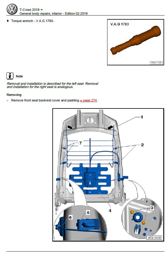
2.15 Removing and installing front backrest
2.16 Removing and installing head restraint
2.17 Removing and installing head restraint guide
2.18 Dismantling and assembling seat pan
2.19 Mounting front seat on seat repair stand
2.20 Removing and installing bracket for seat trim
2.21 Removing and installing storage compartment
2.22 Removing and installing vehicle wallet holder
2.23 Removing and installing seat trim
3 Rear seats
3.1 Assembly overview – bench seat / individual seats
3.2 Assembly overview – locking mechanism
3.3 Assembly overview – head restraint and head restraint guide
3.4 Assembly overview – rear seat backrest
3.5 Assembly overview – rear bench seat
3.6 Removing and installing head restraint
3.7 Removing and installing head restraint guide
3.8 Removing and installing trim for locking mechanism
3.9 Removing and installing locking mechanism for rear seat backrest
3.10 Removing and installing bench seat / individual seats
3.11 Removing and installing backrest cover panel
3.12 Removing and installing seat bench trims
Seat – padding, covers:
1 Front seat covers and padding
1.1 Assembly overview – cover and padding for seat pan
1.2 Assembly overview – cover and padding for backrest
1.3 Assembly overview – seat heating element
1.4 Assembly overview – backrest heater element
1.5 Removing and installing cover and padding for seat pan
1.6 Removing and installing backrest cover and backrest padding
1.7 Separating cover and padding on seat pan
1.8 Removing and installing seat heating element Z6 / Z8
1.9 Removing and installing backrest heating element Z7 / Z9
2 Rear seat covers and padding
2.1 Assembly overview – cover and padding
2.2 Removing and installing covers and padding
2.3 Separating cover and padding
Heating, air conditioner
Technical data:
1 Safety information
1.1 Safety precautions when working on air conditioning systems
1.2 Safety measures when working on vehicles with a start/stop system
1.3 Safety precautions when using testers and measuring instruments during a road test
1.4 Safety precautions when working on the cooling system
1.5 Safety precautions when handling refrigerants
1.6 Safety precautions when working on SCR system
2 Identification
2.1 Identification of heater and air conditioning unit
3 General information
3.1 Type plates
3.2 Notes concerning odours in air conditioned vehicles
3.3 Notes for vehicles with start-stop system
4 Repair instructions
4.1 Rules for cleanliness
4.2 General information
4.3 General repair instructions
4.4 Contact corrosion
4.5 Nuts and bolts
4.6 Routing and attachment of lines
4.7 Fitting radiators and condensers
4.8 Working on refrigerant circuit
4.9 Refrigerant circuit seals
5 Technical data
5.1 Refrigerant capacity
5.2 Refrigerant oil capacities
5.3 Oil distribution
Heating:
1 Overview of fitting locations – heating
1.1 Overview of fitting locations – components not located in passenger compartment
1.2 Overview of fitting locations – components located in front section of passenger
compartment
2 Actuators
2.1 Overview of fitting locations – front actuators
2.2 Removing and installing temperature flap actuator
2.3 Removing and installing air distribution flap actuation unit
2.4 Removing and installing flexible shaft for air distribution
2.5 Removing and installing flexible shaft for temperature flap
3 Heater
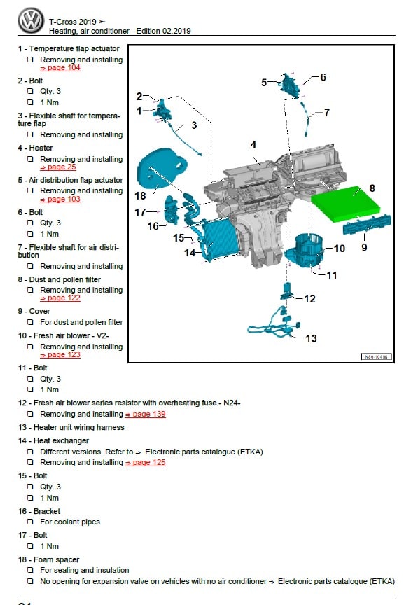
3.1 Assembly overview – heater unit
3.2 Removing and installing fresh air blower V2
3.3 Removing and installing fresh air blower series resistor with overheating fuse N24
3.4 Removing and installing heat exchanger
3.5 Removing and installing heater unit
3.6 Dismantling and assembling heater unit
4 Air duct
5 Operating and display unit
5.1 Overview of operating and display unit
5.2 Removing and installing operating and display unit
6 Other controlling and regulating components
Air conditioning system:
1 Overview of fitting locations – air conditioning system
1.1 Overview of fitting locations – components not located in passenger compartment
1.2 Overview of fitting locations – components located in front section of passenger
compartment
2 Refrigerant circuit
2.1 System overview – refrigerant circuit
2.2 Assembly overview – condenser
2.3 Removing and installing refrigerant circuit pressure sender G805
2.4 Removing and installing expansion valve
2.5 Removing and installing condenser
2.6 Removing and installing desiccant bag or cartridge
2.7 Removing and installing evacuating and charging valves on low and high-pressure side
2.8 Commissioning of air conditioning system after filling refrigerant circuit
2.9 Removing and installing refrigerant line from condenser to air conditioner compressor
2.10 Removing and installing refrigerant line from air conditioner compressor to evaporator
2.11 Removing and installing refrigerant line from air conditioner compressor to evaporator
3 Air conditioner compressor
3.1 Assembly overview – drive unit of air conditioner compressor
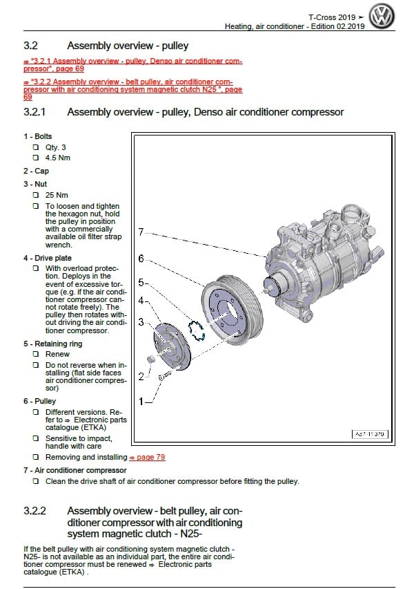
3.2 Assembly overview – pulley
3.3 Removing air conditioning compressor from and installing on bracket
3.4 Removing and installing air conditioner compressor
3.5 Checking high-pressure safety valve on air conditioner compressor
3.6 Removing and installing pulley
4 Control motors
4.1 Overview of fitting locations – front control motors
4.2 Removing and installing defroster flap control motor V107
4.3 Removing and installing front air distribution flap control motor V426
4.4 Removing and installing fresh air and air recirculation flap control motor V154
4.5 Removing and installing left temperature flap control motor V158
4.6 Removing and installing right temperature flap control motor V159
4.7 Removing and installing fresh air/air recirculation, air flow flap control motor V425
4.8 Removing and installing air distribution flap actuator
4.9 Removing and installing temperature flap actuator
4.10 Removing and installing flexible shaft for temperature flap
4.11 Removing and installing flexible shaft for air distribution
5 Front heater and air conditioning unit
5.1 Assembly overview – heater and air conditioning unit
5.2 Assembly overview – evaporator housing
5.3 Removing and installing evaporator
5.4 Checking auxiliary air heater element Z35
5.5 Removing and installing auxiliary air heater element Z35
5.6 Removing and installing heater and air conditioning unit
5.7 Removing and installing holder for heater and air conditioning unit
5.8 Dismantling and assembling heater and air conditioning unit
5.9 Removing and installing air distribution housing
5.10 Removing and installing dust and pollen filter
5.11 Removing and installing fresh air blower V2
5.12 Removing and installing fresh air blower control unit J126
5.13 Removing and installing heat exchanger
5.14 Removing and installing coolant pipes on heat exchanger
5.15 Removing and installing evaporator temperature sensor G308
5.16 Removing and installing flexible shafts
5.17 Removing and installing condensation drain
5.19 Removing and installing fresh air blower series resistor with overheating fuse N24
6 Air duct
6.1 Assembly overview – air duct and air distribution in passenger compartment
6.2 Removing and installing driver side footwell vents
6.3 Removing and installing front passenger side footwell vents
6.4 Removing and installing rear footwell vent
6.5 Removing and installing forced ventilation for passenger compartment
6.6 Checking forced ventilation for passenger compartment
6.7 Removing and installing fresh air intake
6.8 Removing and installing cover for fresh air intake
6.9 Removing and installing air intake duct
6.10 Removing and installing air duct for defroster vent
6.11 Removing and installing air duct for centre vent
7 Operating and display unit
7.1 Overview of operating and display unit
7.2 Removing and installing operating and display unit
8 Other controlling and regulating components
8.1 Removing and installing sunlight penetration photosensor G107
8.2 Removing and installing ambient temperature sensor G17
8.3 Removing and installing humidity sender for air conditioning system G260
8.4 Removing and installing left vent temperature sender G150
8.5 Removing and installing right vent temperature sender G151
8.6 Removing and installing footwell vent temperature sender G192
Maintenance
1 Engine list
2 Service work
2.1 Information about flexible or fixed service
2.2 Service tables
3 General information
3.1 Raising vehicle with lifting platform or trolley jack
3.2 Entries in service schedule
3.3 Severe operating conditions
3.4 Vehicle data sticker
3.5 Connecting vehicle diagnostic tester
3.6 Vehicle identification number
3.7 Countries with hot climate
3.8 Country overview for diesel not compliant with EN 590
3.9 Country overview for petrol not compliant with EN 228
3.10 Engine code and engine number
3.11 Countries with high levels of dust
3.12 Type plate
3.13 Shortened intervals for spark plug replacement
4 Descriptions of work:
4.1 Swivel joints and suspension link mountings: inspecting
4.2 Automatic headlight control and static cornering light: checking function
4.3 Battery (12V): checking battery terminal clamps for secure seating
4.4 Battery (12V): checking with battery tester (always refer to workshop manual)
4.5 Status of battery (12V): reading – sending diagnosis protocol via online connection
4.6 Front passenger front airbag: checking key switch and “ON/OFF function”
4.7 Tires: checking condition, wear pattern, tire pressure and tread depth
4.8 Brake and clutch system: changing brake fluid
4.9 Brake system and shock absorbers: inspecting for leaks and damage
4.10 Brake fluid level: checking
4.11 Brakes, front and rear: checking thickness of pads/linings and condition of brake discs/ drums
4.12 Diesel fuel filter: draining
4.13 Diesel fuel filter: renewing
4.14 Diesel particulate filter: checking
4.15 Electric windows: checking positioning (open and close functions)
4.16 Fault memory of all systems: reading with vehicle diagnostic tester ,correcting possible faults according to repair guidelines
4.17 Boots: inspecting
4.18 Interior and exterior body: inspecting for corrosion with doors and flaps open
4.19 Poly V-belt: renewing
4.20 Poly V-belt: check condition
4.21 Cooling system: checking frost protection and coolant level
4.22 Air filter: cleaning housing and renewing filter element
4.23 Multi-purpose additive for diesel fuel: adding
4.24 Multi-purpose additive for petrol fuel: adding
4.25 Engine and components in engine compartment: inspecting for leaks and damage (from
above and below)
4.26 Engine compartment cover (noise insulation) “bottom”: removing and installing
4.27 Engine oil level: checking
4.28 Engine oil: draining; renewing oil filter and filling engine oil
4.29 Engine oil: capacities and specifications
4.30 Road test: performing (driving behavior, noises, air conditioner etc.)
4.31 Wheel securing bolts: tightening to specified torque
4.32 Reducing agent (AdBlue®/DEF): replenishing
4.33 Reducing agent (AdBlue®/DEF): changing
4.34 Tire Pressure Loss Indicator: calibrating
4.35 Tire repair set: checking
4.36 Window wash/wipe system and headlight washer system: checking function
4.37 Headlight adjustment: checking halogen headlights
4.38 Headlight adjustment: checking LED headlights
4.39 Headlight adjustment: checking fog lights
4.40 Service interval display: resetting
4.41 Service interval display: recoding
4.42 Track rods: checking clearance, attachment and boots
4.43 Dust and pollen filter: cleaning housing and renewing filter element
4.44 Transportation mode: switching off
4.45 Transportation devices: removing blocking pieces
4.46 Clock and date: setting
4.47 Underbody: inspecting for damage to underbody sealant, underbody panels, routing of lines, plugs
4.48 Toothed belt (petrol engines): renewing
4.49 Camshaft drive toothed belt (diesel engines): renewing
4.50 Spark plugs: renewing
5 Exhaust emissions test
5.1 Exhaust emissions test for petrol engines
5.2 Exhaust emissions test for diesel engines
6 Glossary
7 —Change history—
Removed 5-speed manual gearbox 0AH
Technical data:
1 Safety information
2 Identification
3 Technical data
3.1 Allocation gearbox – engine
3.2 Calculation of gear ratios
3.3 Capacities
4 Overview – power transmission
5 Electrical components
6 Repair notes
6.1 General repair instructions
Clutch:
1 Clutch mechanism
1.1 Assembly overview – clutch release mechanism
1.2 Repairing clutch release mechanism
2 Clutch
2.1 Assembly overview – clutch
2.2 Removing and installing clutch
Controls, housing:
1 Selector mechanism
2 Removing and installing gearbox
3 Transporting gearbox
4 Gear oil
5 Dismantling and assembling gearbox
5.1 Schematic overview – gearbox
5.2 Assembly overview – gearbox
5.3 Assembly overview – cover for gearbox housing and 5th gear
5.4 Assembly overview – clutch housing
5.5 Assembly overview – shafts, differential, selector mechanism
5.6 Assembly overview – selector forks
5.7 Repairing selector forks
5.8 Dismantling and assembling gearbox
6 Gearbox housing, clutch housing
6.1 Assembly overview – gearbox housing and clutch housing
6.2 Repairing gearbox housing
Gears, shafts:
1 Input shaft
1.1 Assembly overview – input shaft
1.2 Dismantling and assembling input shaft
1.3 Renewing input shaft seal
2 Output shaft
2.1 Assembly overview – output shaft
2.2 Dismantling and assembling output shaft
Final drive – differential:
1 Oil seals
1.1 Overview of fitting locations – seals
2 Differential
2.1 Assembly overview – differential
2.2 Dismantling and assembling differential
2.3 Adjusting differential
Removed 5-speed manual gearbox 0DF and 0D0
Technical data:
1 Safety information
2 Identification
3 Technical data
3.1 Allocation gearbox – engine
3.2 Capacities
4 Overview – power transmission
5 Electrical components
6 Repair notes
6.1 General repair instructions
Clutch:
1 Clutch operation
1.1 Assembly overview – clutch release mechanism
1.2 Repairing clutch release mechanism
2 Clutch
2.1 Assembly overview – clutch
2.2 Removing and installing clutch
Controls, housing:
1 Selector mechanism
2 Removing and installing gearbox
3 Transporting gearbox
4 Gear oil
5 Securing to engine and gearbox support
6 Dismantling and assembling gearbox
6.1 Schematic overview – gearbox
6.2 Assembly overview – gearbox
6.3 Assembly overview – cover for gearbox housing and 5th gear
6.4 Assembly overview – clutch housing
6.5 Assembly overview – shafts, differential, selector mechanism
6.6 Assembly overview – selector forks
6.7 Repairing selector forks
6.8 Dismantling and assembling gearbox
7 Gearbox housing, clutch housing
7.1 Assembly overview – gearbox housing and clutch housing
7.2 Repairing clutch housing
Gears, shafts:
1 Input shaft
1.1 Assembly overview – input shaft
1.2 Dismantling and assembling input shaft
1.3 Renewing input shaft seal
2 Output shaft
2.1 Assembly overview – output shaft
2.2 Dismantling and assembling output shaft
Final drive – differential:
1 Oil seals
2 Differential
2.1 Assembly overview – differential
2.2 Dismantling and assembling differential
2.3 Adjusting differential
Removed 6-speed manual gearbox 0AJ
Technical data:
1 Safety information
2 Identification
3 Technical data
3.1 Capacities
4 Overview – power transmission
5 Electrical components
6 Repair notes
6.1 General repair instructions
Clutch:
1 Clutch mechanism
1.1 Assembly overview – clutch release mechanism
1.2 Repairing clutch release mechanism
2 Clutch
2.1 Assembly overview – clutch
2.2 Removing and installing clutch
Controls, housing:
1 Selector mechanism
2 Removing and installing gearbox
3 Transporting gearbox
4 Gear oil
5 Securing to engine and gearbox support
6 Dismantling and assembling gearbox
6.1 Overview – gearbox
6.2 Assembly overview – gearbox
6.3 Assembly overview – gearbox housing cover
6.4 Assembly overview – clutch housing
6.5 Assembly overview – shafts, differential, selector mechanism
6.6 Assembly overview – selector forks
6.7 Repairing selector forks
6.8 Dismantling and assembling gearbox
7 Gearbox housing, clutch housing
7.1 Assembly overview – gearbox housing and clutch housing
7.2 Assembly overview – gearbox housing cover
7.3 Repairing gearbox housing
7.4 Repairing gearbox housing cover
Gears, shafts:
1 Input shaft
1.1 Assembly overview – input shaft
1.2 Dismantling and assembling input shaft
1.3 Renewing input shaft seal
2 Output shaft
2.1 Assembly overview – output shaft
2.2 Dismantling and assembling output shaft
Final drive – differential:
1 Seals
1.1 Overview of fitting locations – seals
2 Differential
2.1 Assembly overview – differential
2.2 Dismantling and assembling differential
2.3 Adjusting differential
Running gear, axles, steering
Technical data:
1 Safety information
1.1 Safety measures when working on vehicles with a start/stop system
1.2 Safety precautions when working on subframe
2 Repair instructions
2.1 Leaks at shock absorbers
2.2 Noises from shock absorbers
2.3 Checking shock absorbers when removed
2.4 Steering rack
2.5 Gaskets and seals
2.6 Nuts and bolts
2.7 Electrical components
2.8 Raising suspension to unladen position (vehicles with coil springs)
3 Evaluating accident vehicles
3.1 Check list for evaluating running gear on accident vehicles
4 Waste disposal
4.1 Releasing gas and draining front gas-filled shock absorbers
4.2 Releasing gas and draining rear gas-filled shock absorbers
Front suspension:
1 Front axle
1.1 Overview of fitting locations – front axle
2 Subframe
2.1 Assembly overview – subframe
2.2 Removing and installing subframe without steering rack
2.3 Removing and installing subframe with steering rack
2.4 Removing and installing anti-roll bar
2.5 Removing and installing coupling rod
2.6 Fixing position of subframe
2.7 Lowering subframe
3 Suspension strut, upper suspension link
3.1 Assembly overview – suspension strut, upper suspension link
3.2 Removing and installing suspension strut
3.3 Repairing suspension strut
4 Lower suspension link, swivel joint
4.1 Assembly overview – lower suspension link, swivel joint
4.2 Removing and installing lower suspension link
4.3 Checking swivel joint
4.4 Removing and installing swivel joint
4.5 Renewing bonded rubber bush for lower suspension link
5 Wheel bearing
5.1 Assembly overview – wheel bearing
5.2 Removing and installing wheel bearing housing
5.3 Removing and installing wheel bearing unit
6 Drive shaft
6.1 Assembly overview – drive shaft
6.2 Loosening and tightening threaded connections of drive shaft
6.3 Removing and installing drive shaft
6.4 Removing and installing drive shaft heat shield
6.5 Dismantling and assembling drive shaft
6.6 Checking outer constant velocity joint
Rear suspension:
1 Rear axle
1.1 Overview – rear axle
1.2 Removing and installing rear axle
2 Axle beam
2.1 Assembly overview – axle beam
2.2 Renewing bonded rubber bush for axle beam
2.3 Removing and installing cladding for axle beam
2.4 Removing and installing stone deflector for axle beam
3 Suspension strut, shock absorber, spring
3.1 Assembly overview – suspension strut, shock absorber, spring
3.2 Removing and installing shock absorbers
3.3 Repairing shock absorber
3.4 Removing and installing spring
4 Wheel bearing assembly, trailing arm
4.1 Assembly overview – wheel bearing
4.2 Removing and installing wheel bearing unit
Self-levelling suspension:
1 Vehicle level sender
1.1 Assembly overview – rear vehicle level senders
1.2 Removing and installing rear vehicle level senders G76 / G77
Wheels, tires, vehicle geometry:
1 Wheel alignment
1.1 Notes for wheel alignment
1.2 Conditions for testing
1.3 Test preparations
1.4 Specifications for wheel alignment
1.5 Setting vehicle to initial position for wheel alignment
1.6 Wheel alignment procedure
1.7 Necessity of wheel alignment
1.8 Vehicle data sticker
1.9 Adjusting camber at front wheels
1.10 Adjusting camber on rear axle
1.11 Adjusting toe at rear axle
1.12 Adjusting front axle toe
1.13 Checking maximum wheel lock
1.14 Basic setting of steering angle sensor G85
Steering:
1 Steering wheel
1.1 Assembly overview – steering wheel
1.2 Removing and installing steering wheel
2 Steering column
2.1 Assembly overview – steering column
2.2 Checking steering column for damage
2.3 Handling and transporting steering column
2.4 Removing and installing steering column
2.5 Removing and installing intermediate steering shaft
2.6 Removing and installing control unit for electronic steering column lock J764
3 Steering rack
3.1 Assembly overview – steering rack
3.2 Removing and installing steering rack
3.3 Removing and installing bellows
3.4 Removing and installing track rod
3.5 Removing and installing track rod ball joint
4 Sensors
4.1 Removing and installing steering angle sender G85
















Avaliações
Não há avaliações ainda.